I’ve been working my way through the lessons in the SunFounder LCD Ultrasonic Relay Sensor Electronic Bricks Starter Kit. The kit comes with a manual, and the early experiments have pretty detailed steps with electronics diagrams.

But by the time you get to the stopwatch experiment (lesson 13) there are no more diagrams, so I was left to figure out how to connect the 4-digit 7-segment display. My display had the part number SMA420564, and it had 12 pins. I couldn’t find a spec sheet for it, to understand which pins referred to which segment/digit. After a bit of trial and error, I figured it out:
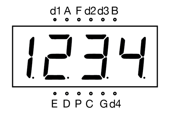
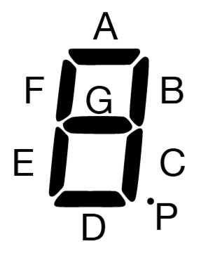
The way I figured it out which pin mapped to which was to adapt the example program that came with the kit to light all segments at once (i.e. “8.”) and then plug/unplug wires until I figured out which was which. I don’t really know the pin numbers, but as long as you know which digit/segment they light, that’s enough. The pins d1, d2, d3, and d4 correspond with each digit, with d1 being the first on the left. The pins with capital letters correspond with the segments A-G of the 7-segment character. The naming convention appears to be quite standardized. The diagram below shows which letter corresponds with which segment:
Here’s a wiring schematic to show which pins of the Arduino each pin goes to. Note that in the diagram below, the LED display is rotated 90º clockwise:
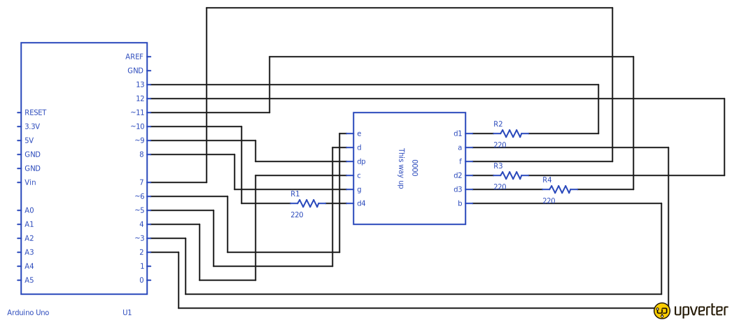
I used Upverter to create the diagram, and you can access it directly on the Upverter site.
With everything wired, it was time to try the code. The kit I had came with one of those small CDs, so I actually downloaded it from the Sunfounder web site. It’s lesson #13 in the Ultrasonic Kit for Arduino here. (NOTE: The original URL doesn’t work, but I found a ZIP of the entire set of lessons for the Ultrasonic Kit, and also posted the source for lesson #13 as a Gist.) When I tried to validate the stopwatch, it failed with the following error:
Timer1 was not declared in this scope
Turns out that there are some C++ libraries that the Sunfounder example code relies on, which weren’t in my environment. I found this blog post that talks about the error, and there’s a link to download the TimerOne library. After downloading it I wasn’t really sure what to do with the .h and .cpp files. I tried placing them in the same directory as my .ino file, but that didn’t help. Eventually I figured out that you have to import it via the Arduino IDE (Sketch>Import Library>Add Library… and then select the folder that contains the TimerOne.cpp and TimerOne.h files.
With that done, I was able to burn the program to my Arduino, and now have a happy stopwatch:
